LLC "MСC-Shaftproject"
Technologies
Preparation of shafts in severe mining and geological conditions, in loose water-flooded rocks is a complicated engineering task that cannot be solved without application of special working methods and innovative developments.
Fibre concrete
Fibre concrete has been used as a material of load-bearing structures for over 40 years, including over 20 years - as a material of tunnel lining structures.
Fiber reinforcement allows compensating for main deficiencies of concrete - low tensile strength and impact brittleness. As compared to regular bar reinforcement, fiber reinforcement brings economic benefit during erection and manufacturing of structures due to the following:
1
Significant reduction in labour input to manufacturing of reinforcement cages, cutting down the cost of structure repair because of fewer internal defects such as non-vibrated zones behind the reinforcement and higher resistance to cyclic impacts (drying - dampening, positive - negative temperatures, vibration, etc.) for prefabricated, cast-in-situ and sprayed-concrete structures.
2
Enhanced stability of the lined working, better safety of works when lining the working with sprayed concrete during sinking of tunnels, faster and safer recovery works in case of emergency - with the use of sprayed fiber concrete.
Use of bolting
Bolting is intended for stiffening the rock massive and enhancing stability thereof by bolting rock layers of different strength.
Purpose of road lining reinforcement:
-1-
Reduction of front abutment pressure impact on road stability.
-2-
Re-use of roads for ventilation purposes (airway, gas-draining channel, combined scheme of breaking face blowing-over) and availability of escape ways.
-3-
Implementation of pillarless panel removal (lower amount of preliminary underground workings, higher coal recovery factor)
-4-
Operation of the power-driven system without face-end support.
-5-
Ensuring stability of peripheral rocks in low-depth underground workings.
Bolting used

Combination
bolts
bolts
Rope
bolts
bolts
Support
structures
structures
Fixed with
capsules
capsules
Fixed with capsules and by blow-in
USE OF THE SHAFT SINKING SYSTEM WITH PARALLEL SETTING OF SHAFT LINING
Shaft sinking is performed with the shaft sinking system (without drilling-and-blasting operations). Shaft lining is performed while sinking.
Driving a vertical shaft with the SBM shaft boring machine
Shaft boring machines (SBM) are designed for drilling vertical shaft shafts, including in difficult geological and climatic conditions.
Shaft sinking using the SBM shaft sinking system from Robbins (USA) is possible with parallel construction of permanent support.
The SBM shaft tunneling system has a number of design features:
➢ Independent cutting head stroke from 1.0 to 2.0 m
➢ Shield (provides continuous protection from rock and covers the surface from the bottom to the location of the shaft support)
➢Technological sites for parallel support erection, drilling of advanced exploration wells and wells for preliminary plugging of the massif.
➢ Complex positioning system and direction control.
➢ System for removing rock from the bottom to the buckets of the vertical conveyor (elevator).
The SBM tunneling machine is a complex of working platforms. Working platforms are delivered to the construction site and stored at the assembly site.
SBM is assembled using mobile crane equipment such as Liebherr with a lifting capacity of 25 t or similar, working platforms are assembled into assembly modules. The composition of SBM is determined for each project individually.
After complete assembly of the system, the technical ROP can reach:
➢ Rocks 150-200 MPa: from 1.0 to 1.5 m / h (from 720 to 1080 m / month).
➢ Rocks 100-150 MPa: from 1.5 to 2.25 m / h (from 1080 to 1620 m / month).
➢ Rocks (fractured) 150-200 mPa: from 1.5 to 2.5 m / h (from 1080 to 1800 m / month).
Given that the commercial ROP will be between 25% and 35% of the public time, the ROP can be taken into account:
➢ Rocks 150-200 MPa: 225 m / month.
➢ Rocks 100-150 MPa: 330 m3 / month.
➢ Rocks (fractured) 150-200 MPa: 360 m / month.
(Exclusive Agreement with The Robbins Company (USA) No. 201419-C-S-1, which grants LLC "MCC-Shaftproject" the exclusive right to supply mining equipment to Robbins)
Driving an inclined shaft with the TBM boring machine
Driving of inclined shaft shafts using a TBM tunneling machine manufactured by Robbins (USA).
The TBM tunneling systems for mine workings, manufactured by Robbins, which can be used for sinking inclined mine shafts, have a number of design features and advantages that allow you to safely and efficiently drill in geological and hydrogeological conditions of any complexity, including in the presence of aquifers.
TBM tunneling machines are manufactured with a diameter of 1.6 to 15 m and allow you to drill horizontal and inclined workings at a speed of 300 to 600 m / month or more (finished workings).
Structurally, TBM tunneling complexes are made with one shell (TBM Robbins Single Shield) and double shell (TBM Robbins Double Shield).
TBM Robbins Single Shield systems are simpler in design and require less capital investment. The short length of the TBM Robbins Single Shield provides a minimum turning radius.

Complexes TBM Robbins Double Shield are equipped with a telescopic shell-screen, spacers as well as protective and tail screens and allow to build a support simultaneously with driving of mine workings and provide high productivity.


The TBM tunneling machines regardless of their design are made for maximum productivity, safety and process automation.
To ensure a continuous production process and a high level of safety, TBM tunneling complexes are equipped with a set of Difficult Ground Solutions (DGS) options, which allow driving of inclined shafts and other workings even in difficult geological conditions:
To ensure a continuous production process and a high level of safety, TBM tunneling complexes are equipped with a set of Difficult Ground Solutions (DGS) options, which allow driving of inclined shafts and other workings even in difficult geological conditions:
- the presence of a multi-speed drive system for the rock cutting body provides several operating modes: high speed, low torque for hard rocks and low speed, high torque for soft plastic and loose rocks. This feature allows you to select the optimal mode of operation of the rock cutting body, which excludes jamming in the zones of faults and fractured rocks.
- the presence of a stepped screen of the rock-breaking body and the use of bentonite solution during driving allows driving in unstable rocks prone to the development of additional pressure on the shell of the complex.
- the presence of increased traction and thrust jacks provide the possibility of additional acceleration in a short stroke, creating sufficient force to pull out the jammed tunneling complex.
- the presence of special conductor openings in the frontal part of the complex and its shell, as well as manipulators in its inner part with the possibility of installing drilling equipment allows drilling exploration and backfill wells, if necessary.
- the presence of the Water Inrush Control system allows isolating the tunneling complex and ensuring the safety of personnel, as well as protecting the machine from flooding in the event of an emergency breakthrough of water into the bottomhole zone
- the presence of a control system that warns of the development of pressure on the shell of the complex from the host rocks.

Driving a vertical shaft with the SBR shaft boring machine
Vertical shaft sinking system SBR has been developed and currently manufactured for DMC Mining services (contractor of BHP Billiton) to be used in construction of the mining and processing combined works on the potash field in Canada, as well as in construction of two shafts in Starobinskoye potash salt field for the Nezhin mining and processing combined works Slavkaliy, the Republic of Belarus.
SHAFT SINKING SYSTEM SBR
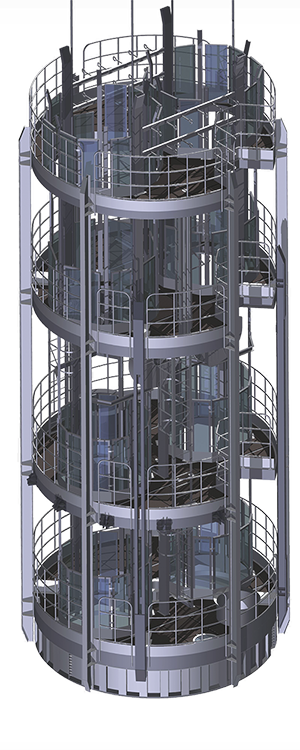
Basic components
Use of the proven soil recovery technology.
A cutting unit structure similar to that of VSM.
A gripper device for sinking process stabilization.
Transportation of broken muck via a vacuum pump.
Integrated lining setting system.
Powerful ventilation system
Process platforms may be equipped in accordance with requirements
A cutting unit structure similar to that of VSM.
A gripper device for sinking process stabilization.
Transportation of broken muck via a vacuum pump.
Integrated lining setting system.
Powerful ventilation system
Process platforms may be equipped in accordance with requirements
The weight of SBR system at 9 m diameter is 300 tons.
WATERPROOFING, PLUGGING AND INJECTIVE MATERIALS
Specialists of LLC "MСC-Shaftproject" use materials for waterproofing recovery by injection of hydro-structural resins by world manufacturers such as BASF, Monova, Zika, MC Bauchemie, etc.
Use of Penetron waterproofer allows preventing the water from penetrating through the concrete bulk even at the quite high hydrostatic pressure. Use of material allows protecting concrete against corrosive fluids: acids, effluents, ground waters, sea water. Concrete treated with Penetron acquires resistance to carbonates, chlorides, sulphates, nitrates, etc. Use of Penetron enhances figures of impermeability to water, strength, freeze-thaw resistance of concrete that persist even under high radiation effect. The material is used for waterproofing of surfaces having pores, cracks with opening width under 0.4 mm. Waterproofing of surfaces having pores, cracks with opening width over 0.4 mm as well as of welds, joints, interfaces, abutments, utility entrances is achieved with Penekrit combined with Penetron.
The main goal of Masterflex is sealing of dams, surface isolation, prevention of cracking on the rock surface on the roof and sides, surface protection against environmental impact, waterproofing. Due to its adhesive properties the material wraps the rock mass and penetrates in cracks and small voids on the working surface thus making a solid air-tight film.
Two-component coating Spray-On Plastics by RockWeb, which is applied by spraying is a 100% dry, solvent-free substance intended for soil stabilization in ore fields. A unique property of RockWeb allows clogging big cracks in the surface layer of the rock.
Tram system with bottom unloading.
Developed and implemented at the Severny-Gluboky mine (JSC Kola MMC).

The system of transporting ore with bottom unloading with a complex solution allows providing very high productivity due to the fact that when using it, the loading time of the train is reduced. The continuous unloading of trolleys is carried out, the speed of technological operations increases, the load factor increases and the spillage of the rock (ore) mass is reduced.
The system for transporting ore with bottom unloading consists of a set of technological equipment, which includes:
1. Trolleys with bottom unloading. The peculiarities of these trolleys are not only the folding bottom, but also the overlap of the end walls of adjacent trolleys, while there is no free space between the upper parts of the end walls of adjacent trolleys. The special design of the trolleys ensures continuous loading and unloading of trolleys, as well as the absence of ore spillage.
2. Station of bottom unloading (unloading unit) for continuous unloading of trolleys, which includes sections of the unloading curve, support beams, bearing rollers.
3. Broaching mechanism that allows unloading a train with one locomotive. The broaching mechanism allows you to fix the speed of the train regardless of whether the broaching mechanism pulls the train or slows it down.
4. Hatching device. Designed for continuous loading on the move. Spillage of ore during loading of the train is excluded practically.
5. Locomotive. Locomotives of special design including those with two motors and four-wheel drive, which increases the productivity of the haulage complex.
125124 Moscow,
3-rd Yamskogo Polya Ul., 18, floor 7
Zolotoy Vek Business Center
3-rd Yamskogo Polya Ul., 18, floor 7
Zolotoy Vek Business Center
© All rights reserved.
LLC "MСC-Shaftproject"
LLC "MСC-Shaftproject"


Phone: +7 (495) 252-11-77

mcc@shaftproject.ru